
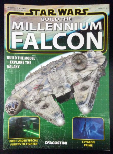
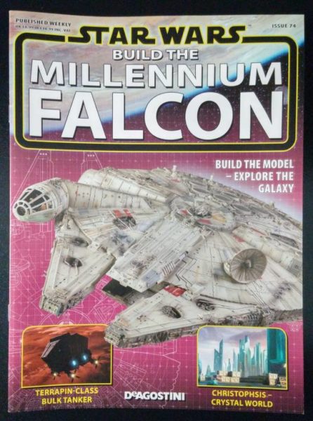
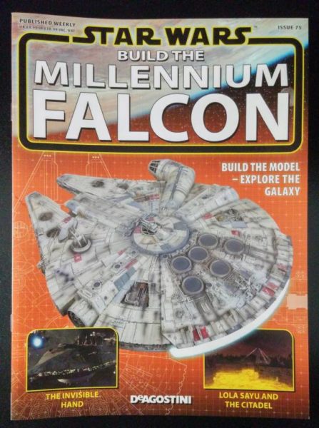
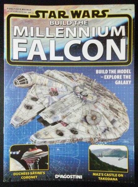
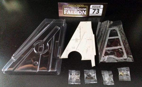
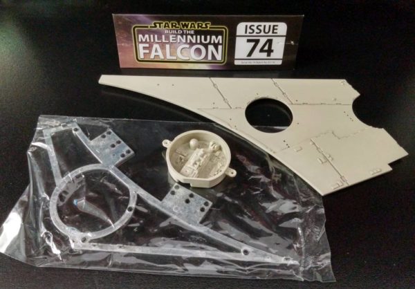
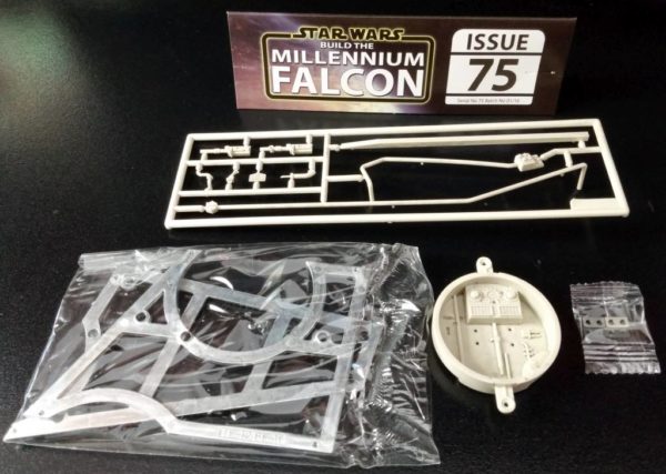
Millennium Falcon Build Journal No. 21: Issues 73-76
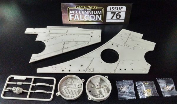
The Arrival
It seems that the closer I get to the end of the build, more milestones keep popping up. Not only am I beginning another major part of the Millennium Falcon, but I am now 75% of the way through the build. Woo-hoo!
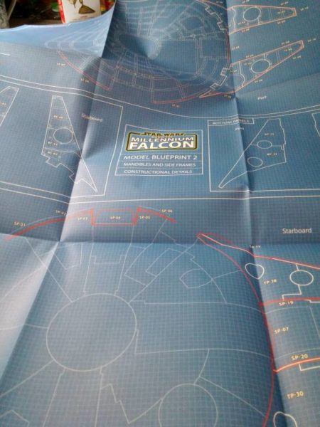
Along with the shipment comes another fold-out blueprint for the mandibles and side panels.
Skipping Ahead: Upper Hull Greeblies
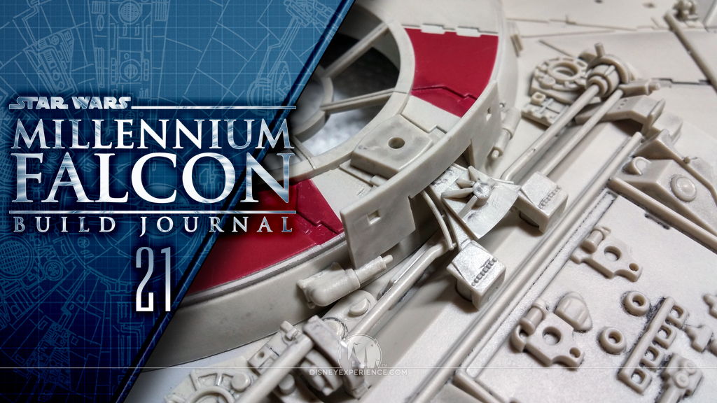
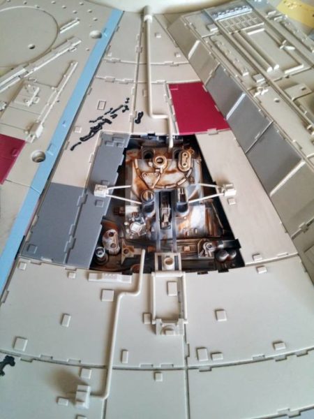
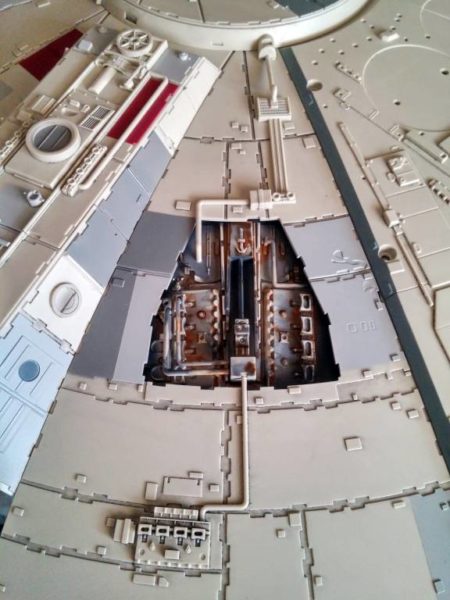
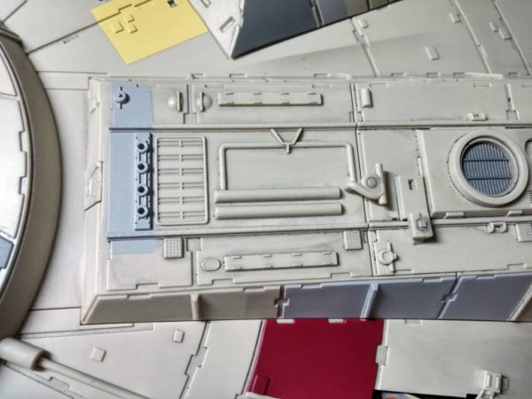
At this point in the build, I have accumulated several sprues with greeblies that attach to the upper hull. These get attached near the end of the build. Other than being easily damaged, I see no reason why I couldn’t put them on right now. I keep my model on a dedicated storage shelf (see Build Journal No. 9), and I treat it with care.
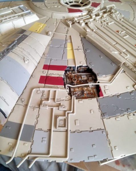
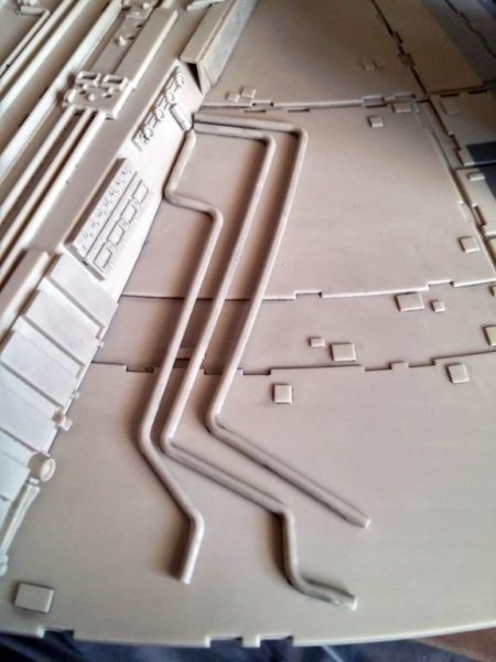
Most of the greeblies are pipes, and I used reference photos to find where they go. It wasn’t too hard since the parts are grouped together on the sprues depending on the areas of the model to which they are glued.
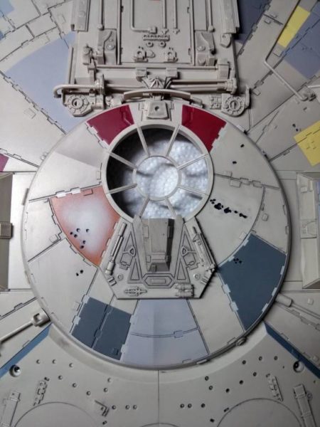
The rest of the greeblies fitted onto the starboard hall, the upper turret cover (note the turret guard which the bottom turret does not have), and the cockpit access tube.
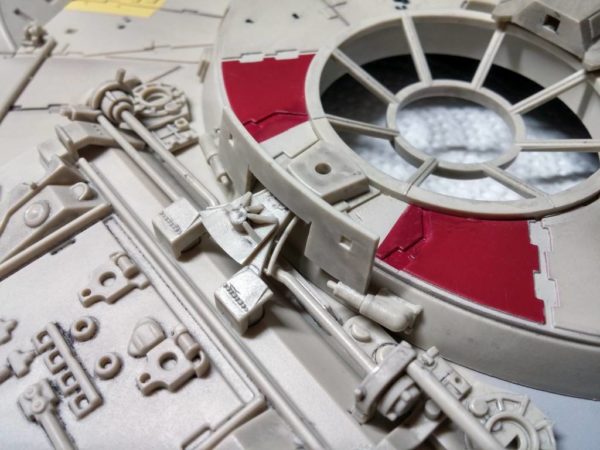
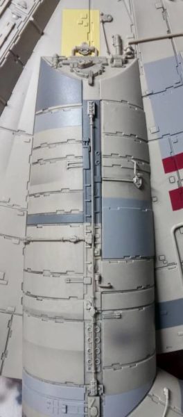
Before attaching the greeblies to the access tube, I had to assemble the two tube pieces by screwing them together. The parts were still loose, so I also glued them together.
With the access tube assembled, I dry-fitted it back onto the hull (it was awesome to finally see the cockpit attached to the upper hull). I glued on the greeblies where the end of the access tube meets the hull. I still wanted to be able to remove the access tube for future painting, so I made sure that the greeblies were either glued to the access tube or the hull. Then, I added the details to the rest of the access tube. It was a little fiddly, but I got it done.
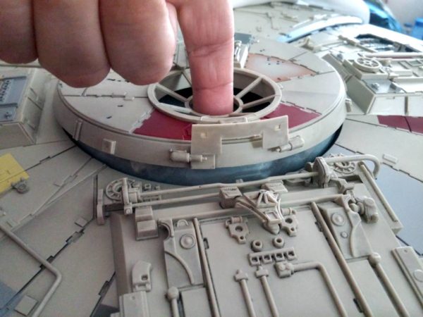
In the last Build Journal, I mentioned that I did not screw down the turret cover because it would make removing the cutaway plating difficult. This left me with the dilemma of how to secure the turret cover while keeping it loose. Well, the upper hull greeblies seem to have solved that problem for me.
Two of the pipes (near the engine cover) extend all the way up the the turret cover (I didn’t glue them to the turret cover). Well, low and behold, the two pipes hold the back end of the turret cover down, allowing the front end to open. Problem solved . . . for the time being.
Mandible Assembly
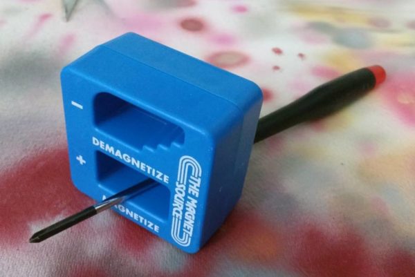
While I was looking at magnets for an unrelated project, I found a handy-dandy tool for magnetizing screwdrivers. Magnetic screwdrivers are awesome at grabbing the little screws and holding onto them. I already had magnets but nothing strong enough to create a strong magnetic field. This little gem works like a charm, and it can demagnetize tools! What a great little find.
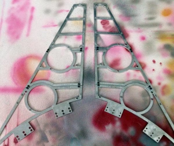
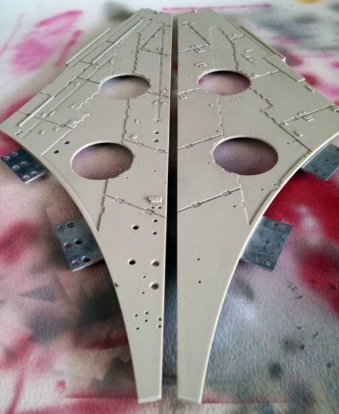
The assembly of the two halves of the starboard mandible was pretty straight-forward. It’s just a few metal frames topped with a few hull plates. There’s nothing challenging here.
Painting
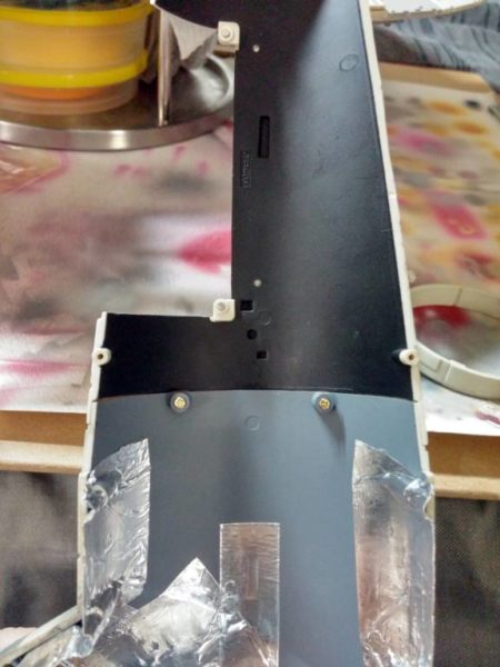
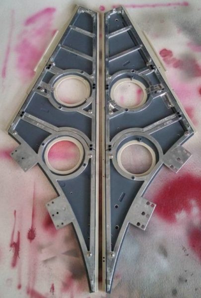
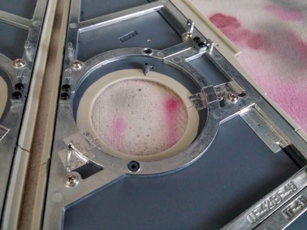
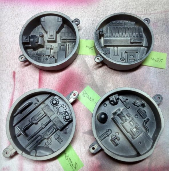
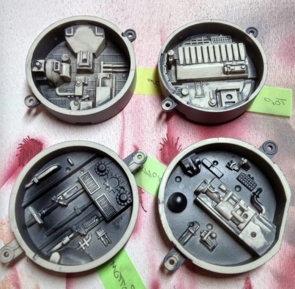
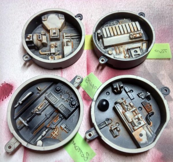
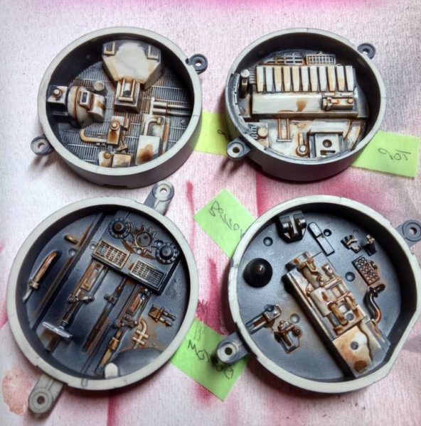
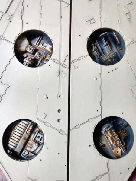
The only bit of painting required were of the machine recesses for the mandible halves using the same process that I used on the upper hull recesses. Studying my reference photos of the actual filming model, I noted that the bottom recesses are much darker than the upper ones.
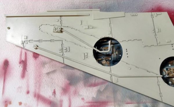
With the recesses painted, I screwed them to the mandible halves. I also looked at upcoming issues to glue the remaining sprue parts to the mandible.
Prev Journal Entry | Next Journal Entry
Both the post author and this website have not received any compensation for writing this post. Both the post author and this website have no material connection to the third-party brands, products, or services that have been mentioned. Some of the links in the post above are “affiliate links.” This means that if you purchase the item, we will receive a commission. As an Amazon associate, we earn from qualifying products. This is being disclosed in accordance with the Federal Trade Commission’s 16 CFR, Part 255: “Guides Concerning the Use of Endorsements and Testimonials in Advertising.”


Do you have a thought about this post? Why not leave a comment . . .